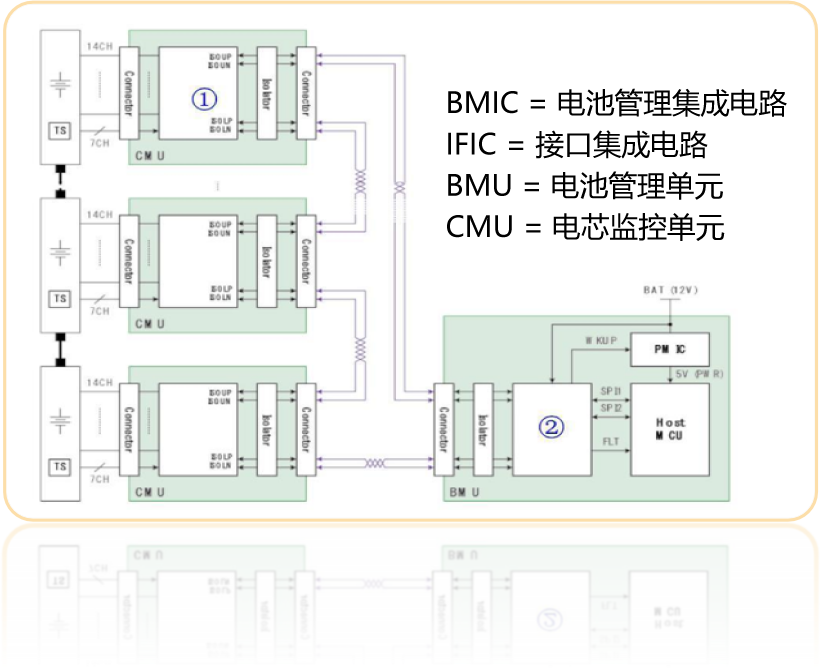

BMS Chipset: BMIC and IFIC


Analysis of The Advantages of BMIC Chip Technology
1) Easier BMS design and development
(1)Active functions in BMIC and IFIC
(2)Save the function of the host MCU
(3)More easily replicable features
(4)Quick fault handling and fault classification
2) System level redundant fault tolerance
(1)Fault tolerant data interface (SPI and electrical isolation)
(2) BMIC-IFIC,IFIC-MCU
3) Active Function
(1)IFIC actively identifies fault categories (for single CU)
(2)BMIC initiates fault handling (for IFIC)
(3)Active fault signal (BMIC/IFIC)
(4)Active Fault Interruption and Classification (IFIC)
4) High speed data interface
Up to 4mbps daisy chain
1) Following the ASIL-D Standard
2) AEC-Q100 Grade 1
3) Fault handling time
(1)Active fault signal sent to IFIC
(2)Active fault interruption to MCU
4) Fault coverage rate
(1)Dual channel measurement (voltage/temperature)
(2)Internal self-test function
(3)Fault tolerance for each data interface failure
(4)Active fault monitoring/signal/interruption/classification
5)Fault tolerance
(1)SPI Data Interface (IFIC-MCU)
(2)Chrysanthemum Chain (BMIC-IFIC)
(3)Cell voltage/temperature measurement
1)Circular interface of a single IFIC
(Superior to Maxim/ADI/NXP solution)
2) Bidirectional daisy chain
(Superior to Maxim's solution)
3) IFIC integrates RTC function
(Superior to all other solutions)
4)VBAT operability of IFIC
(Superior to Maxim/ADI/NXP solution)
Comparative Analysis of BMIC Competitors
Comprehensive Benchmarking Against overseas Giants
| Brand | XSL | Maxim | ADI (LTC) | NXP | TI | INFINEON | |
| Model | EXCS3001 | MAX17853 | LTC6811 | MC33771C | BQ79616 | TLE9012AQU | |
| AEC-Q100 | Grade 1 | Grade 1 | Grade 1 | Grade 1 | Grade 1 | Grade 1 | |
| Number of Voltage Channels for Battery Cells | 14 | 14 | 14 | 14 | 14 | 14 | |
| Number of AUX Channels | |||||||
| 7 | 6 | 5 | 7 | 9 | 5 | ||
| Cell voltage error (V cell=4.2V) | ±1.5mV | ±2mV | ±2.8mV | ±3.9mV | - | ±5.8mV | |
| ADC | 16b(SD X 4EA) | 12b(sar x 1ea) | 16b(SD X2EA) | 16b(mix X3EA) | 12b(sarx 2ea) | 16b (SD X 13EA) | |
| Secondary CVM | 0(ADC) | X | O | X | O(ADC) | X | |
| Hardware protector (overvoltage/undervoltage) | O(adc &d-comp) | O(adc &d-comp) | X | X | O(adc &d-comp) | O(adc &d-comp) | |
| Chrysanthemum Chain Data Communication | Direction | two-way x2EA | one-way x4EA | two-way x2EA | two-way x2EA | two-way x2EA | two-way x2EA |
| I/F | ISOSPI(2CH,4Mbps) | ISOSPI(2CH,4Mbps) | ISOSPI(2CH,4Mbps) | ISOSPI(2CH,4Mbps) | ISOSPI(2CH,4Mbps) | ISOSPI(2CH,4Mbps) | |
| Maximum number of connected ICs | 32 | 32 | - | 32 | - | 32 | |
| Chrysanthemum Chain Fault Report | Function | O | X | O | X | O | O |
| Additional communication lines are Required | x (Using data communication channels) | x (Using data communication channels) | x (Using data communication channels) | x (Using data communication channels) | x (Using data communication channels) | x (Using data communication channels) | |
| ASIL | D | D | Follow | C | D | C | |
| Package | eLQFP-64(10B) | LQFP-64(10B) | SSOP-48 | eLQFP-64(10B) | HTQFP-64(10B) | PG-TQFP-48(7B) | |

Advantages of BMS Chip Technology


Electric Vehicle Field